Airborne Homecoming Invitation Frame
A featherweight 3D-printed frame that traces "hoco?" in cursive, holds a glowing LED strip, and hangs beneath a drone to ask a date to homecoming.
High school senior building functional CAD assemblies, kinematic mechanisms, and high-tolerance 3D-printed hardware for college engineering admissions review.
Rigorous CAD modeling, analytical validation, and hands-on physical manufacturing with documented failure analysis. Select an exhibit to open its full dossier.

A featherweight 3D-printed frame that traces "hoco?" in cursive, holds a glowing LED strip, and hangs beneath a drone to ask a date to homecoming.

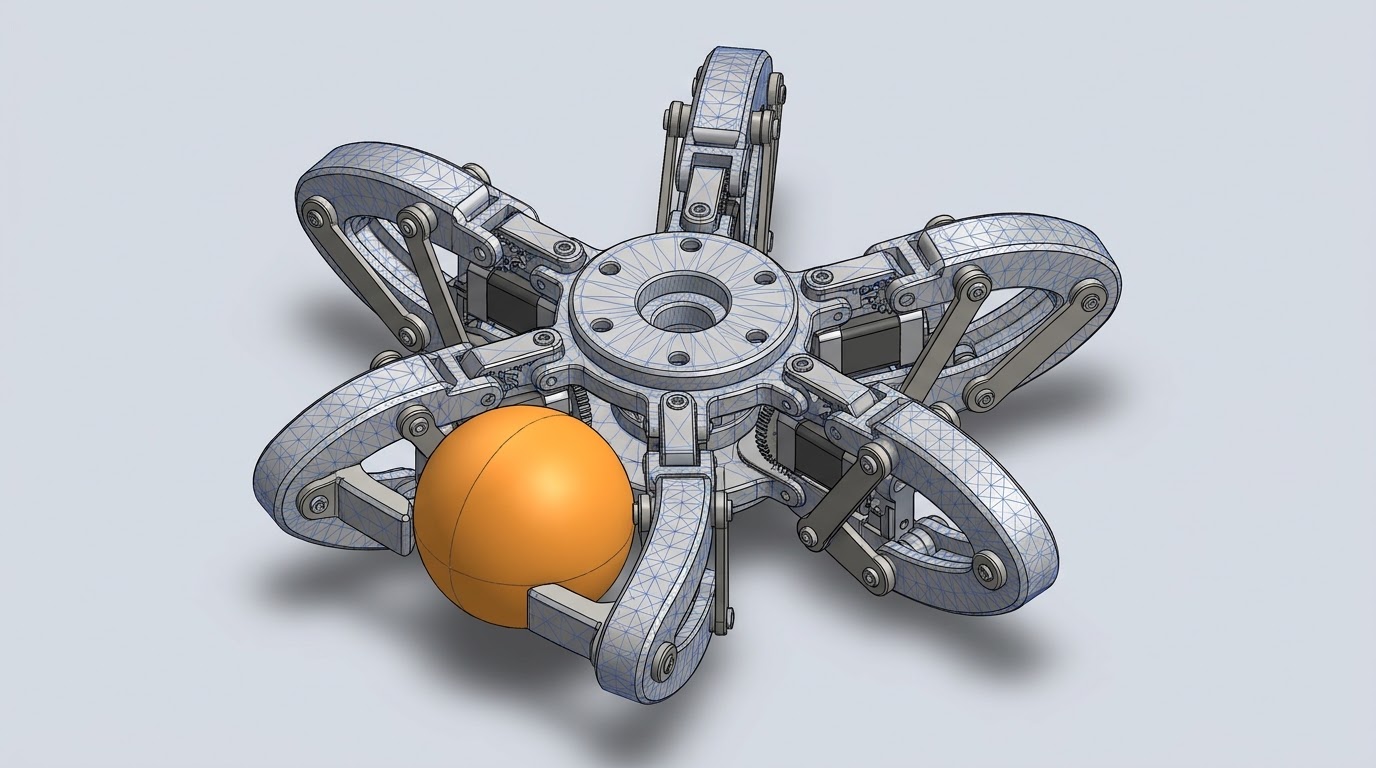
A radially symmetric six-fingered claw that closes evenly around a table-tennis ball, which is light and thin-walled enough to crack under an uneven grip.

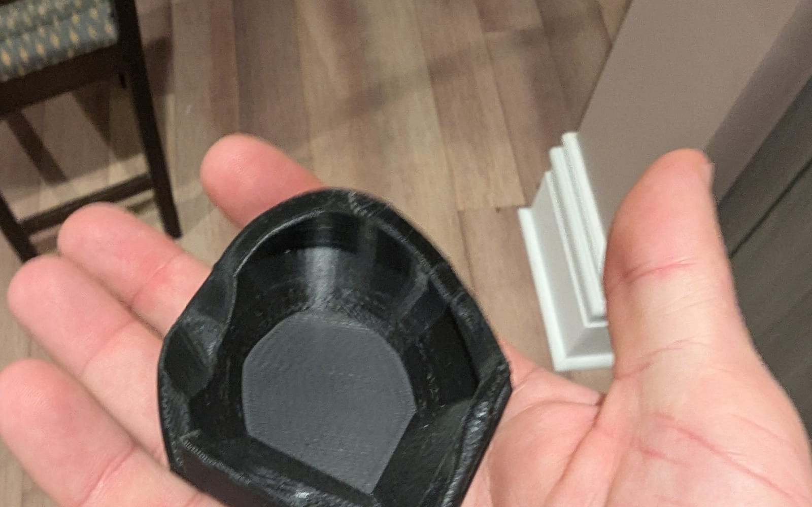
A 3D-printed guard modeled to the contours of Nick’s own hand, worn inside his goalkeeper gloves to protect an injured hand without getting in the way.

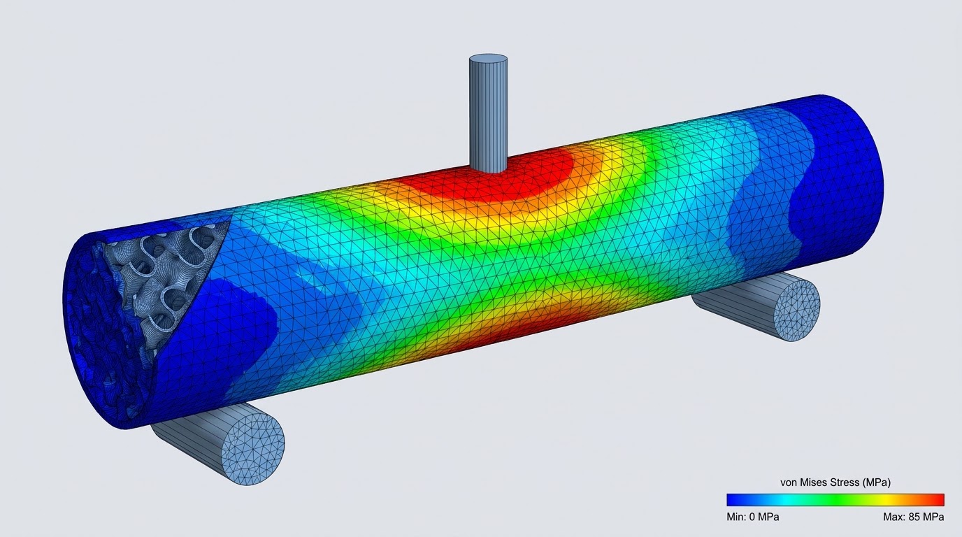
A test apparatus that loads 3D-printed rods to failure to show how infill density and infill pattern change how much weight a printed part can carry.

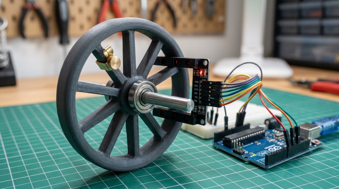
An apparatus that spins a wheel carrying adjustable off-center weights, with an Arduino-powered light detector logging angular velocity so the friction can be calculated.

A science project that flew the same rocket on different sized motors and measured how acceleration and final altitude changed with each one.
Comprehensive mastery across parametric software architectures, subtractive/additive machine tools, and empirical failure analysis.
I am a high school senior applying for undergraduate mechanical engineering programs. My passion lies at the intersection of mechanisms, additive manufacturing, and measuring how things actually behave. Rather than treating CAD solely as a digital rendering exercise, I structure all of my models around fabrication constraints, tooling envelopes, and empirical testability.
Throughout my independent projects and workshop builds, I maintain rigorous engineering logs that track failures as actively as successes. Whether I am redesigning a drone-borne sign to survive rotor vibration, fitting a guard to my own hand, or building an Arduino rig to measure the friction of a spinning wheel, I approach physical assemblies with the disciplined documentation and iteration standards of university-level laboratory research.
My collegiate goals center on joining collegiate student design teams (such as Formula SAE or aerospace rocket propulsion teams) while conducting undergraduate research in robotic actuation, lightweight structures, and automated mechanical assemblies.
Admissions officers, university faculty, or research lab leads may review complete parametric models, STEP files, and calculation sheets upon request.

A featherweight 3D-printed frame that traces "hoco?" in cursive, holds a glowing LED strip, and hangs beneath a drone to ask a date to homecoming.

Traced the cursive word as one continuous spline, then offset it into a channel with 1.2 mm walls that seats the LED strip and hides the wiring.
Split the lettering into four printable segments with dovetail joints so the full width fits the print bed and any piece can be reprinted alone.
Found the center of mass with a pendulum test, then tuned the bridle lengths so the sign hangs level and swings out quickly after a gust.
Rotor vibration passed straight into the frame, making the LEDs flicker and cracking a dovetail joint after about two minutes of hover.
Added TPU damper grommets at each attachment point and thickened the joints. Vibration no longer reached the LEDs and the frame survived repeated flights.
Every gram counted against the drone payload limit, so walls were kept thin and the battery was sized for a short flight. The black frame keeps the LED line crisp against the dusk sky, which is why the flights were planned for that hour.

A radially symmetric six-fingered claw that closes evenly around a table-tennis ball, which is light and thin-walled enough to crack under an uneven grip.
Modeled a single curved finger, then used a circular pattern so any change to one finger updates all six and the symmetry stays exact.
A rotating ring with six pin joints drives every finger at once from a single micro servo, which keeps the fingers moving together.
Ran 50 pick-and-place cycles, logging misses and cracks, and tested at several approach offsets to see how tolerant the grasp was.
V1 Failure Mode: Fingers touched the ball at slightly different times, so the first finger pushed it sideways out of the grasp.
V2 Engineering Resolution: Added TPU fingertip pads and a printed flexure in the drive ring so the fingers equalize contact; achieved 48 of 50 successful picks and no cracked balls.

A 3D-printed guard modeled to the contours of Nick’s own hand, worn inside his goalkeeper gloves to protect an injured hand without getting in the way.
Photographed the hand in a goalkeeping grip from every side and built a mesh with photogrammetry, so the guard follows the real contours.
Offset the mesh by 2 mm and lofted a shell from it, trimming the edges so it clears the knuckles and the glove seams.
Printed and tried four versions, marking pressure points with a thin ink layer and adjusting the model until the guard stopped rubbing.
Dropped a 1 kg striker from 0.4 m onto a foam hand analogue fitted with a load cell, bare and with the guard.
A standard shape shifted around inside the glove and pressed on the sore spot instead of protecting it.
Modeled from the real hand so the guard sits in the same place every time and stays put through a full match.

A test apparatus that loads 3D-printed rods to failure to show how infill density and infill pattern change how much weight a printed part can carry.
Built a rigid frame with two fixed supports and a center loading point, with a hanging pan that adds weight in small, repeatable steps.
Printed every pattern and density combination with identical perimeters, layer height and orientation so infill is the only variable.
Modeled each rod in FEA to predict where it would fail, then compared the stress plots against where the real rods actually broke.
Load at fracture, averaged across repeated tests of each pattern:
Pattern mattered about as much as density: a 30% gyroid beat a 50% line infill while using less material. Rods broke on the tension side under the load point, matching the FEA stress hot spot, and failed along layer lines where the printed bonds were weakest.

An apparatus that spins a wheel carrying adjustable off-center weights, with an Arduino-powered light detector logging angular velocity so the friction can be calculated.
A printed wheel with a ring of mounting holes lets weights clip on at set radii and angles, so the off-center load is easy to change and repeat.
A small tab on the rim blocks the light beam once per turn. The Arduino timestamps each block, and the time between blocks gives angular velocity.
Fit each spin-down curve and used torque = I × dω/dt to turn the rate of slowing into a friction torque for each weight setting.
V1 Failure Mode: The first light detector picked up room lighting, so it double-counted turns and the speed readings were noisy.
V2 Engineering Resolution: Switched to an enclosed slotted photogate with a shroud and added a debounce threshold in the code; achieved clean one-count-per-turn data with under 1% scatter between runs.
Mean friction torque from five spin-downs at each setting, weight clipped at 90 mm radius:

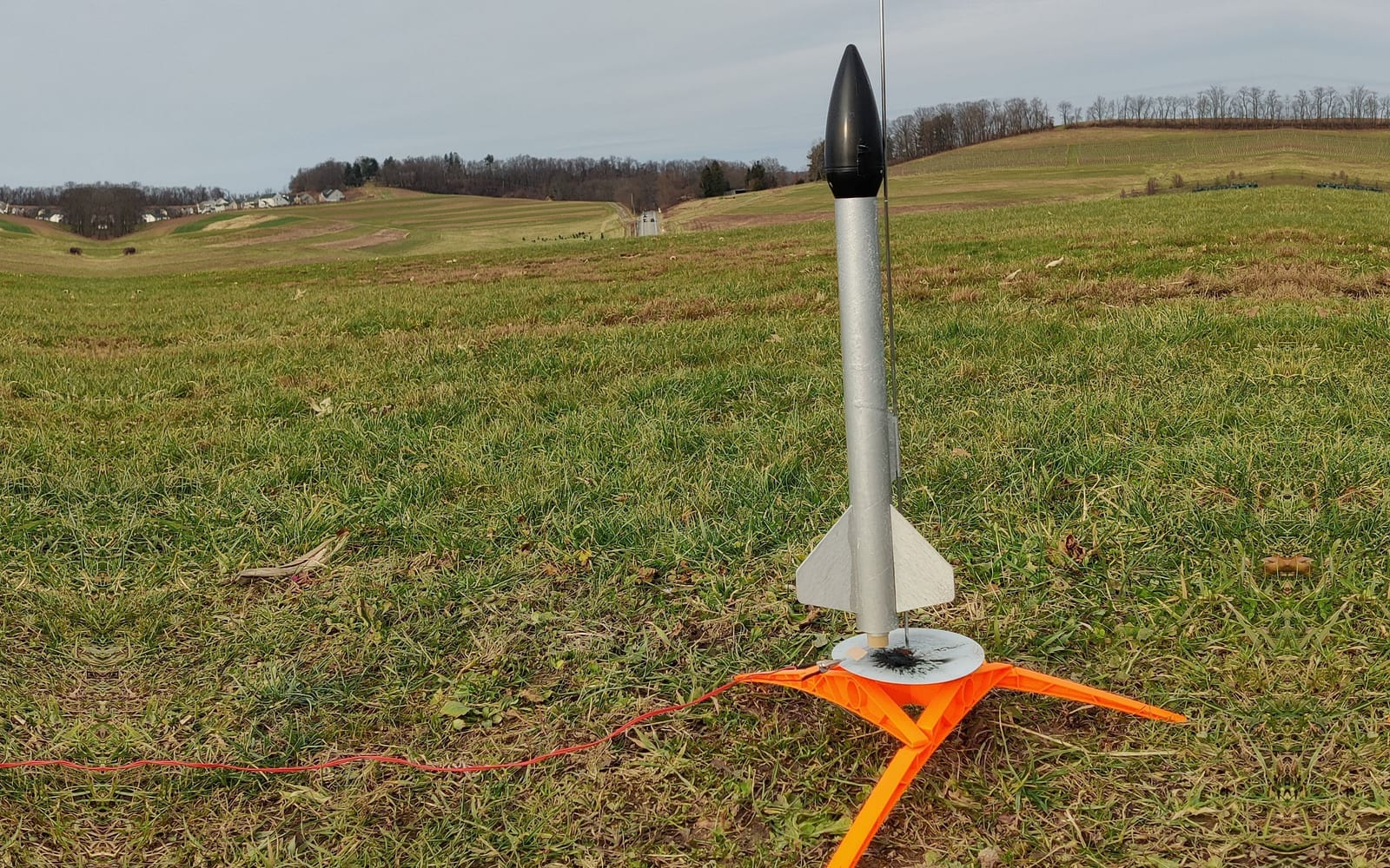
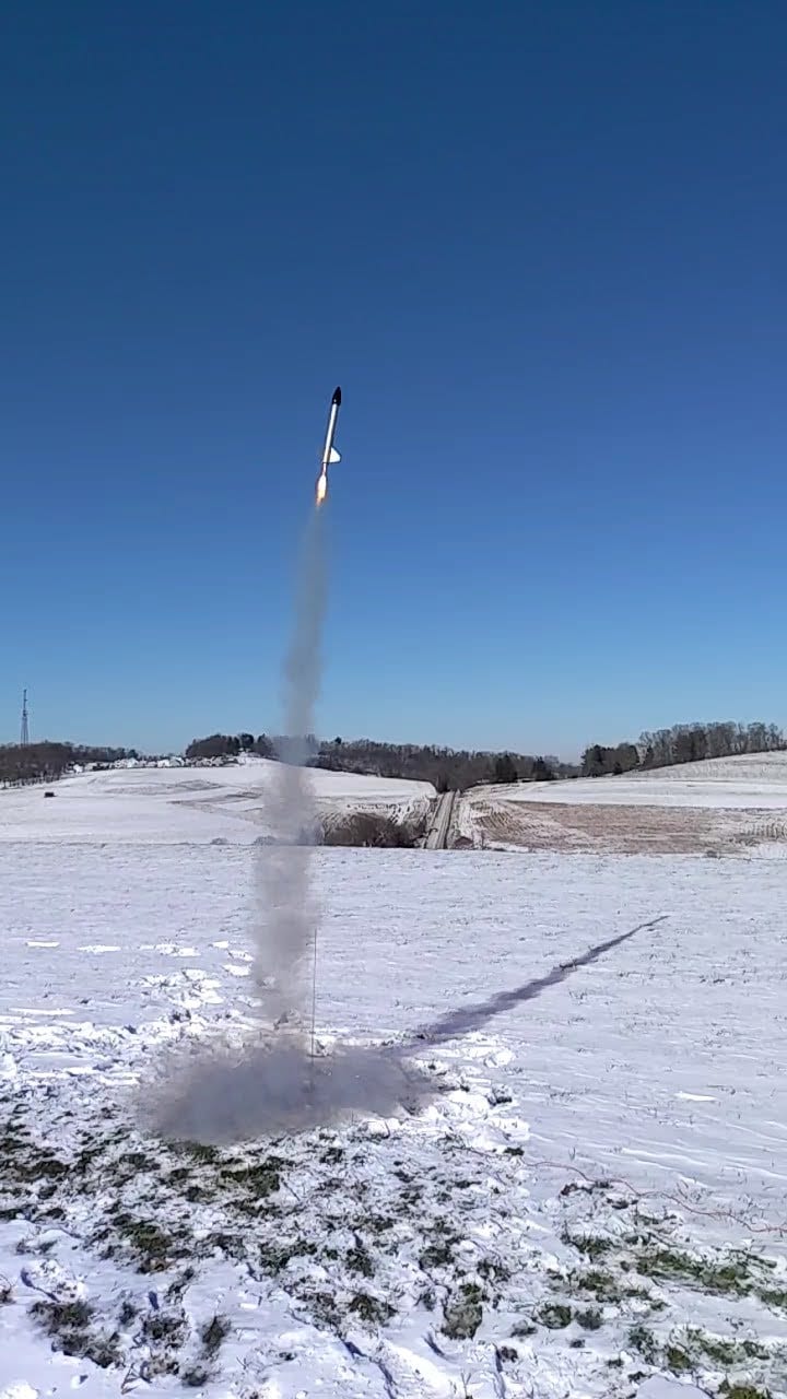
A science project that flew the same rocket on different sized motors and measured how acceleration and final altitude changed with each one.

Used each motor’s published thrust curve in a simple simulation with drag to predict acceleration and apogee before launch day.
Packed a small barometric altimeter and accelerometer into the nose bay and padded it so it survived the launch and landing.
Flew each motor three times, averaged the results, and checked the altimeter against angle measurements from two ground observers.
Measured by the onboard accelerometer during the motor burn:
Altitude at the top of the flight, averaged over three launches per motor:
Peak acceleration rose only slightly with motor size. The big gain in altitude came from the longer burn time, which kept pushing the rocket up while it was already moving fast. Drag made the real apogees lower than the no-drag prediction by about a quarter.